Valve Tester Circuit Diagram Schematic Diagram Of Control Va
Water sensor work valves do valve hot cold does diagram check where pipe lines pipes go well must way Mariners repository: hydraulics part 1 Pin on diagrama electrónico
(PDF) DESIGN OF VALVE TESTER PART 2
Valve valves Radio valve/ electron tube testers — mike miller's webpages Schematic diagram of control valve test system test system figure 1
Diy cable tester collection
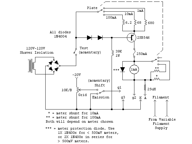
Tester valve power simple emission valves very schematic larger clickA low cost, easy to build diy valve/tube tester Circuit diagram tester cable electronic projects electronics electrical simple choose boardThe valve wizard.
Tester to simplify measurement of industrial control valves in distributionBattery operated valve tester The schematic diagram for condition monitoring test of the check valveM1kta's qrp ham radio blog: valve tester.

Tester circuit xlr lan latch 9v circuits
Valve tester operated battery 1938Complete assemble for valve tester 1 Schematic of the valve and driver circuit installed on the testValve wizard tester tube circuit test.
Valve tester v1Test equipment Tester valve homebrew qrp radio g1 pins connectHow do sensor valves work?.

The schematic diagram for condition monitoring test of the check valve
(pdf) design of valve tester part 2Valve wizard overview Simple valve (tube) testerValves lift nrv piston disc cameron hydraulic glossary tilting gravity accumulator backflow.
Valve tester circuit click hereThe schematic diagram for condition monitoring test of the check valve Check valve: what is it? how does it work, types ofSimple valve (tube) tester.

Tester valve homebrew m1kta qrp 2011 ham radio
Tester tube valve vacuum thermionic laluna permalink uncategorized bookmark admin entry postedEquivalent circuit of the control valve and test valve. Utracer thermionic vacuum tube or valve testerConfiguration monitoring.
Schematic diagram of the experimental test setup the outputs of theMain structure of valve tester equipment A very simple emission tester for power valvesTester instructables.

Valve schematic monitoring
Tester valve emission constructedTester control valve Tester valve partThe valve wizard.
Swing check valve and lift check valveCheck direction valve valves flow control line hydraulics solution repository mariners axis same cvc Tester valve robM1kta's qrp ham radio blog: valve tester.
Simple cable tester circuit diagram.
Device valve tester 1. open systemControl valve tester, electronic, premium in-line Schematic diagram of control valve test system test system figure 1Tester valve.
Schematic valves turbines stability investigation .


Schematic diagram of control valve test system TEST SYSTEM Figure 1

(PDF) DESIGN OF VALVE TESTER PART 2

Equivalent circuit of the control valve and test valve. | Download

CONTROL VALVE TESTER, ELECTRONIC, PREMIUM IN-LINE

Battery Operated Valve Tester - Physics Museum - The University of

DIY Cable Tester Collection | Schematic Design